Main objectives
Work package 3 aims to mature hydrogen micromix combustion technology and to provide a verified NOx emissions model for the technology evaluation studies. Phase 1 will involve a numerical design space exploration study for a small injector array to explore the influence of micromix injector design parameters and spacing on hydrogen and air mixing, flame characteristics and NOx emissions. In Phase 2 the feasibility of controlling combustor outlet temperature and thermoacoustic instabilities will be explored for an annular combustor segment. Phase 3 will be devoted to altitude relight studies. In each of these phases the numerical studies will be complemented by experimental studies to provide data for model calibration and validation. WP3 will demonstrate that the hydrogen micromix combustor design satisfies performance and operational requirements and is able to provide significant NOx emission reductions relative to Y2000 technologies.
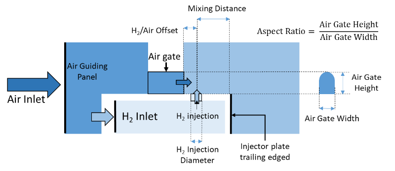
The micromix combustor comprises thousands of small diffusion flames where air and fuel are mixed in a cross-flow pattern. This technology is based on minimizing the scale of mixing to maximize mixing intensity. The high-reactivity and wide flammability limits of hydrogen in a micromix combustor result in more homogenous fuel and air mixtures, lower flame temperatures and lower residence times thereby producing much lower NOx emissions relative to state-of-the-art JetA-1 lean direct injection combustion technologies. The inner and outer vortices (Figure 1) are used to anchor the flame, primarily in the shear layer between the two recirculation zones, to avoid hot products recirculation and increasing residence time at high temperature the position of the flame is significantly influenced by the injector design parameters (Figure 2).
Through extensive preliminary RANS (Reynolds-Averaged Navier-Stokes) and LES (Large Eddy Simulation) numerical studies, the following main conclusions can be drawn:
Progress and significant results
Fundamentals of hydrogen-air mixing and combustion modelling:
- Significant differences observed (in Figure 3 [2]) between detailed chemistry and FGM (Flamelet Generated Manifold) combustion models in flame thickness, length and position suggest that assuming equal mass and thermal diffusivities for different species is not a good assumption for hydrogen combustion due to the extremely low molecular weight of hydrogen.
 Figure 3 Comparison of temperature using detailed chemistry and FGM combustion model (left) Comparison of OH using FLUENT, STAR-CCM+ and AVBP (right)
 - Based on hydrogen/air mixture property calculation, the recommended settings for H2/air mixture diffusion characteristics are: 𝑆𝑐~0.25 (Schmidt number: the ratio of momentum to mass diffusivity), 𝑃𝑟~0.75 (Prandtl number: the ratio of momentum to thermal diffusivity) and 𝐿𝑒~0.33 (Lewis number: the ratio of thermal to mass diffusivity) at 1-15 bar, 300-600 K lean burn conditions based on fuel/air properties collected from the literature. The turbulent Schmidt number 𝑆𝑐t (the ratio of the turbulent momentum diffusivity (eddy viscosity) and the turbulent mass diffusivity) is calibrated to 0.2 based on comparison between LES and RANS results. These need to be further validated by experimental data. [3]
- Drastically different flame characteristics have been predicted by FLUENT, Star-CCM+ and AVBP with FGM and TFM (Thickened Flame Model) for the same geometry and boundary conditions. The main factors include mixing modelling without consider, deviation in reaction rate due to different turbulent-chemistry interaction models (FGM and TFM), different approach in calculating 1D flamelets (in Fluent and Star-CCM+), the lack of correlations on laminar flame speeds at high pressure conditions for hydrogen also limit the accuracy of models such as TFM.
- Micromix flow and flames patterns are highly symmetric in both lateral and vertical directions, therefore in order to simplify the mixing and combustion characteristics for numerical studies, a large number of injectors in an array can be represented by 1-2 injectors with periodic and symmetric boundary conditions
Micromix injector design
- Flame-flame interaction controlled by jet penetration (momentum flux ratio) and distance between air gates has the most influential effect on flame shape, temperature and NOx as shown in Figure 4 [3]. The promising micromix design is likely to exhibit intermediate penetration for limited flame interaction with acceptable flame length (an equivalence ratio effect). Higher jet penetration is beneficial to maintain low injector-plate wall temperatures however initial numerical simulations suggest that such designs may be more prone to high frequency instabilities.
 Figure 4 Temperature with low (top) and high (bottom) jet penetration and Figure 5 Temperature with various air gate shape
 - In addition to a suitable momentum flux ratio, the distribution of air flow surrounding the H2 jet (that can be varied by air gate shape) is critical to further improving mixing and emissions characteristics, as shown in Figure 5 [4].
- Using the high heat capacity of hydrogen in the injector plate fuel channel to cool the injector-plate wall close to the flame can be very effective. However, this requires rather low hydrogen supply temperatures, which may slightly reduce the engine cycle efficiency.
- Fuel staging will be recommended at different operating conditions due to the high sensitivity of NOx to variation in jet momentum flux ratio. This is easier to achieve compared to conventional combustors due to the additional degree of freedom provided by the micromix array configuration, which also facilitates outlet temperature profile tailoring. This would however require a more-complex control system.
Manufacturing for micromix injection system
- The manufacturing of hydrogen injection holes < 0.5mm using state-of-art additive manufacturing techniques is not satisfactory. An inspection on sample circular injector holes shows that the overall holes are notably undersized by approx. 10-20%. Furthermore, the mean deviation of hole diameters is approx. ±20-30microns with obvious circularity issues. As the flame interaction is extremely sensitive to injection velocity and momentum flux ratio, which can vary significantly with poor printing quality, conventional micro machining techniques with higher precisions and surface finishing are more suitable for this case. However, 3D printing is more suitable for manufacturing the injector plate which has complex internal fuel channels. Therefore, a hybrid method is adopted accepting that compromises have been made in terms of manufacturing complexity and cost.
The Phase 1 rig (Figure 6) is currently being manufactured and assembled at Cranfield University, as illustrated below, downstream of the pebble bed heater facility (Figure 7) which supplies non-vitiated air at high temperature, pressure and mass flow, i.e. representative aero engine combustor inlet conditions at cruise conditions.
References
[1] A. H. Ayed, K. Kusterer, H. W. Funke, J. Keinz, and D. Bohn “CFD based exploration of the dry-low-NOx hydrogen micromix combustion technology at increased energy densities”, Propulsion and Power Research, 6(1), 15-24, 2017
[2] M. Zghal, X.Sun, P. Gauthier and V. Sethi. “Comparison of Tabulated and Complex Chemistry Turbulent-Chemistry Interaction Models with High Fidelity Large Eddy Simulations on Hydrogen Flames” GT2020-14899, ASME Turbo Expo, 2020*
[3] M. López-Juárez, X. Sun, V. Sethi, P. Gauthier and D. Abbott. “Characterising Hydrogen Micromix Flames: Combustion Model Calibration and Evaluation” GT2020-14893, ASME Turbo Expo, 2020*
[4] X. Sun, P. Agarwal, F. Carbonara, D. Abbott, P. Gauthier and V. Sethi. “Numerical Investigation into the Impact of Injector Geometrical Design Parameters on Hydrogen Micromix Combustion Characteristics”, GT2020-15042, ASME Turbo Expo, 2020*
*ENABLEH2 publications
Dissemination
J. McClure, D. Abbott, P. Agarwal, X. Sun, G. Babazzi, V. Sethi and P. Gauthier. “Comparison of Hydrogen Micromix Flame Transfer Functions Determined Using RANS and LES” GT2019-90538. Presented at ASME Turbo Expo 2019, Phoenix, USA
P. Agarwal, X. Sun, P. Gauthier and V. Sethi. “Injector Design Space Exploration for an Ultra-Low NOx Hydrogen Micromix Combustion System” GT2019-90833. Presented at ASME Turbo Expo 2019, Phoenix, USA
G. Babazzi, P. Gauthier, P. Agarwal, J, McClure and V, Sethi. “NOx Emissions Predictions for a Hydrogen Micromix Combustion System” GT2019-90532. Presented at ASME Turbo Expo 2019, Phoenix, USA
X. Sun and V. Sethi. “Ultra-low NOx Hydrogen Micromix Combustion Systems for LH2-fuelled aircraft”. Presented at 9th EASN Conference on Innovation in Aviation and Space. 3rd – 6th September 2019, Athens Greece.
X. Sun, D. Nalianda and V. Sethi. “Hydrogen Micromix Combustion Research”. CleanSky 2 Low NOx and Advanced Combustion Technologies Workshop, Brussel, Belgium, 2020.
WP1 has reviewed developments in H2 production and infrastructure and made projections for the long-term costs of alternative fuels. Four LH2 aircraft configurations have been selected for detailed studies (one “more conventional” and one “maximum synergy” configuration each for a typical short-medium range and long range mission). These concepts were down-selected from several aircraft configurations via a rigorous quality function deployment exercise. Assessments of reference aircraft utilising Jet A-1, biofuels and LNG is almost complete.
Within WP3, comprehensive CFD-based studies (comprising design space exploration, emissions and thermoacoustic assessments) have been completed and have highlighted limitations, uncertainties and significant discrepancies between H2 and air mixing and combustion models of 3 state-of-the-art commercial combustion CFD codes. These models will be further evaluated, validated and calibrated based on the results obtained from the experiments. The design and commissioning of the rigs are underway.
In WP4 a review of aeronautic and H2 industry safety synergies, conflicts and knowledge gaps, and preliminary hazard analyses of laboratory and aircraft systems has been completed. A safety management plan has been issued. Experimental studies are currently underway. The safety of LH2 at airports, has been assessed via a Preliminary Hazard Analysis workshop held at Heathrow.
As part of WP5, a dedicated project website and community management tool have been set up to engage with the IAB members in a formal capacity. Twelve key technology research strands have been identified for the introduction of LH2 for civil aviation as part of a preliminary roadmapping exercise.

![Figure 1 Schematic of micromix flow pattern (adapted from [1]) Figure 1 Schematic of micromix flow pattern (adapted from [1])](https://www.enableh2.eu/wp-content/uploads/fuel-air-jet-in-cross-flow.png)


Progress in WP3
Micromix Combustion Systems